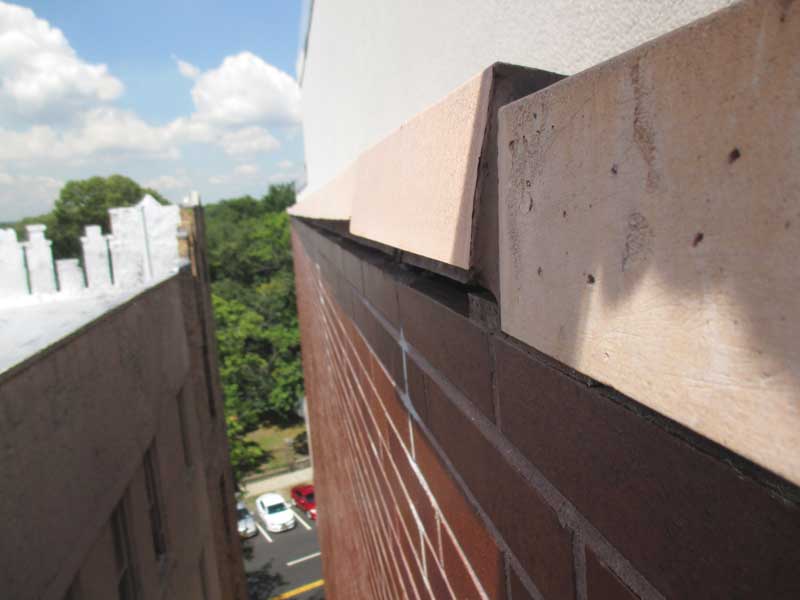
Designing brick veneer for loadbearing exterior walls
The article addresses crucial considerations for designing brick veneer in conjunction with loadbearing exterior walls, specifically focusing on the movement and shrinkage of concrete masonry unit (CMU) backup walls and their implications for brick veneer support. It highlights that concrete masonry walls undergo expansion and contraction due to changes in moisture content and temperature, with the magnitude of these volume changes determined by intrinsic CMU properties and environmental factors like temperature fluctuations and moisture loss.
The National Concrete Masonry Association (NCMA) provides technical guidance, such as NCMA TEK 10-2A on Movement Control, which introduces the Crack Control Coefficient (CCC). The CCC is a critical indicator of anticipated wall movement and is used to manage cracking. It quantifies CMU shortening per unit length, integrating the combined effects of drying shrinkage, carbonation shrinkage, and temperature-induced contraction. The CCC is calculated by summing the coefficients of these three properties, which are influenced by the mix design and production/curing methods of the CMU. The total linear drying shrinkage is determined using ASTM C 426, while carbonation shrinkage, a long-term process, reflects the irreversible reaction between cementitious materials and atmospheric carbon dioxide. Temperature-related contraction is calculated by multiplying the CMU's thermal expansion/contraction coefficient by a specified temperature change.
The CCC typically varies, corresponding to a significant shortening in a 31-meter (100-foot) wall, potentially up to 25 mm (1 inch). Most of this shrinkage occurs within the first few years after construction. Additionally, loadbearing concrete block walls experience long-term shrinkage known as ‘creep,’ which can amount to approximately 3 mm (1/8 inch) per floor. This overall shrinkage of the concrete block wall directly impacts continuous shelf angles, which are typically attached to bond beams at each floor level.
As the CMU loadbearing wall shrinks, the shelf angle can move downwards by approximately 6 mm (1/4 inch) per floor. Concurrently, the brick veneer can expand upwards by about 3 mm (1/8 inch) per floor. To accommodate these movements, a total space of approximately 9.5 mm (3/8 inch) is required beneath the shelf angle at each floor. This space is derived from the sum of the shelf angle’s downward movement and the brick veneer’s upward expansion (1/4 inch + 1/8 inch = 3/8 inch). To effectively absorb this movement, a closed-cell neoprene compressible filler, with 60 percent compressibility, should be 16 mm (5/8 inch) thick and placed within the 16-mm (5/8 inch) thick horizontal expansion joint situated between the top of the brick veneer and the bottom of the shelf angle at every floor.
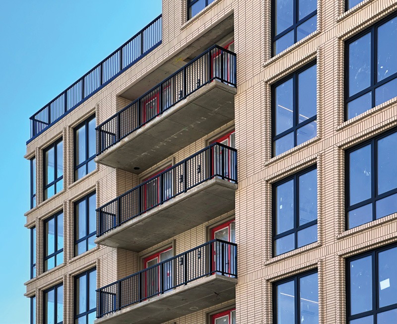
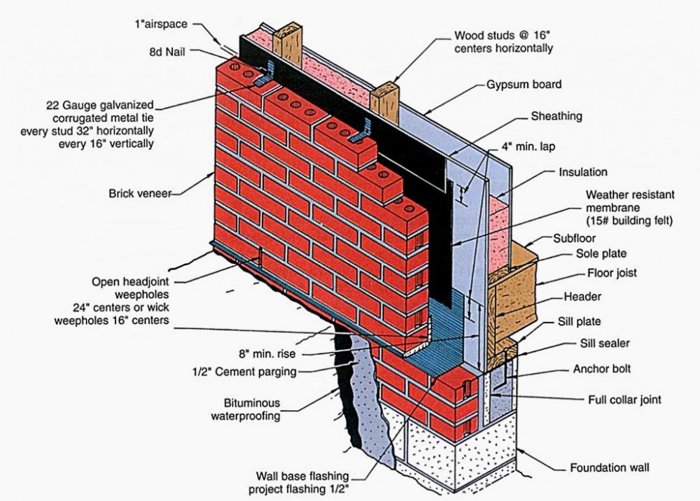
The article provides an example of a six-story apartment building with loadbearing masonry walls. In this case, the building featured 1.2-meter (4-foot) wide window masonry openings, for which loose lintels were specified at the window heads. Notably, continuous shelf angles were not provided to support the brick veneer at each floor level. Instead, the brick veneer was separated from the loadbearing CMU backup wall by an airspace and rigid insulation board and was solely supported by the foundation at the building's base. This highlights a common design scenario and implicitly suggests the importance of proper detailing to manage differential movements between the brick veneer and the loadbearing structure.
#BrickVeneer #LoadbearingWalls #ConcreteMasonry #CMU #Shrinkage #MovementControl #CrackControlCoefficient #ShelfAngles #BuildingDesign #BrickVeneer #LoadbearingWalls #ConcreteMasonry #CMU #Shrinkage #MovementControl #CrackControlCoefficient #ShelfAngles #BuildingDesign
0 comment in total
 No comments yet
You may also like
Statement bricks are the latest design trend

Acme Brick, Tile and Stone – Northwest Arkansas
Nexus Designs curates eight ‘styles’ for PGH Bricks and Pavers
How to incorporate a brick wall in your home
Ten buildings animated by expressive brick facades
Masonry reinvented: One brick at a time
Discover 5 stunning options to use instead of brick facades

Is exposed brick still on trend? Designers debate whether this 'timeless' look really is a classic

Ready To Pick a Patio Pattern? Here Are 12 Designs To Consider
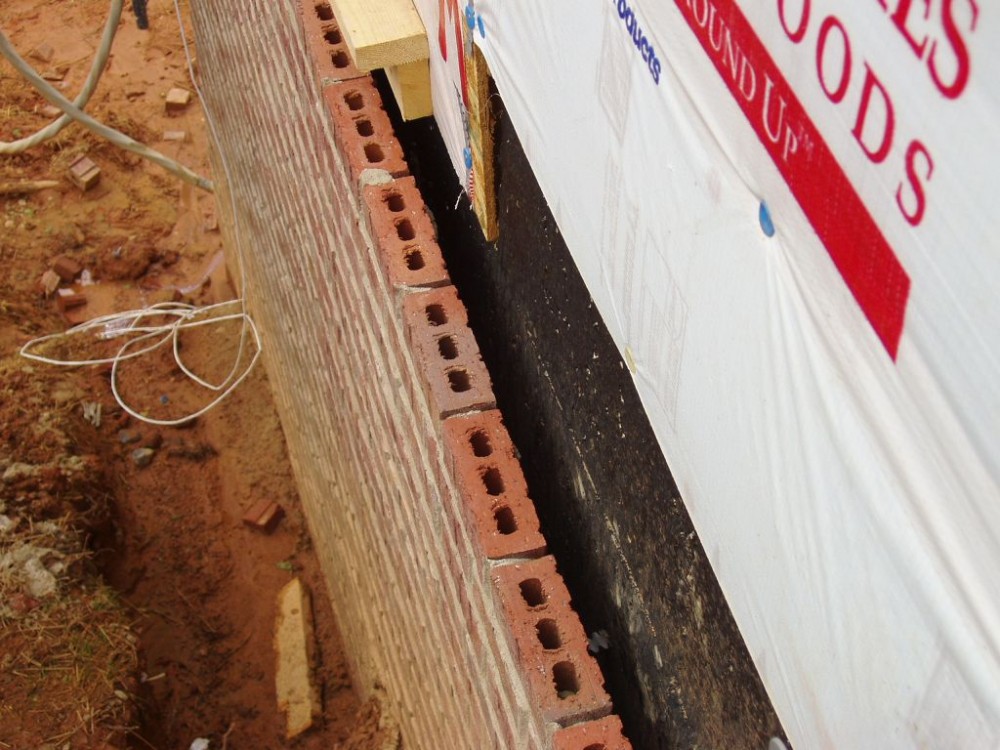
Brick Cladding: Helping keep moisture out
Another brick in the wall
10 of the most popular brick interiors on Dezeen's Pinterest boards
What is brick veneer?

Acme Brick, Tile and Stone – Tulsa
Acme Brick, Tile and Stone – Jackson, TN

Birmingham
Acme Brick, Tile and Stone – El Paso
Acme Brick, Tile and Stone – Shreveport
12 brick floors that will take your breath away
Case Study: Brick Inlay Delivers A Stunning Visual Dynamic Of Concertinaed Jade Brick Tiles